Tempest: Panel Board Removal
You will find the instructions for removing the Tempest panel board below.
Getting inside the Tempest is easy and only requires a screwdriver:
1. First remove all the knobs by pulling straight up, they are tight but not attached (no twisting required).
2. Then unscrew the 6 screws on the back of the Tempest, followed by the 7 screws on the bottom. The lid will be now be free to remove.
3. Place a towel, some bubble wrap, or other soft padding behind the Tempest. The lid is attached to the main board in the bottom portion of the metalwork by a ribbon cable so you’ll want to treat it as a hinge, opening the lid away from you.
4. Disconnect the ribbon cable between the top panel and the main board. You can remove it by hand, by placing your index finger under the cable parallel to the cable header and placing your thumb on top of the cable so you’re pinching it, then rocking back and forth with medium force. DO NOT PULL ON THE CABLE ITSELF
5. Before you remove the screws for the top panel PCB and gain access to the OLED, notice the 2 small ribbons coming from the touch-faders. They are attached to the front panel control board. Using your fingernail with light force only, release the small black locking connectors by sliding them open towards the pads PCB, i.e. in the direction of the fader ribbons and parallel to the top panel PCB. The locking connectors don’t come out completely, they are fully unlocked after moving approximately 3 millimeters.
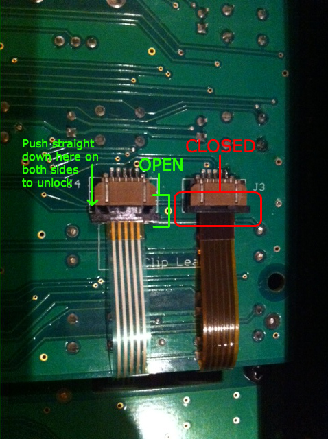
Fader Ribbons
6. Once the locking connector has been released you can easily slide the ribbons out. To put the ribbons back in, simply slide them back in while the locks are in the open position, then close the locks when the ribbons are fully inserted.
7. You can now remove the 11 screws that hold the top panel PCB in place. Don not remove the 4 screws holding the OLED mounts in place. They are marked with a message on the top panel PCB that states “Do Not Remove Screws”. The top panel PCB can now be removed.
8. Reassemble the Tempest in the reverse order. Start by reinstalling the touch-fader ribbons (see step number 6), then reattach the ribbon cable between pads PCB and the top panel PCB. Pay special attention to this ribbon cable, it must remain slightly tucked under the front panel PCB with a bend or you may get crosstalk (noise) on voice 3. This just means leave the cable like you found it initially.
9. Reinstall ribbon cable between the top panel and the main board. Now reinstall the 11 top panel screws, close the lid and reinstall the exterior screws on the back and bottom of the Tempest. Finally, press the knob back into place on the encoder and potentiometer shafts.
10. When everything is reassembled, run the touch-fader calibration routine located in the System menu.
Please contact DSI Technical support if you have any questions regarding this procedure.